Methodologies
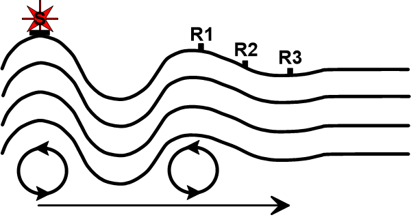
Surface wave (Rayleigh wave) energy, generated using an acoustic source, is recorded at predetermined receiver locations (R1, R2, etc.). A dispersion curve (phase velocity versus frequency) generated from the acquired field data is inverted and used to generate a 1-D shear wave velocity sounding. If additional MASW data sets are acquired at adjacent locations, 2- D or 3-D shear-wave velocity models can be created.
Modified from “Introduction to Geotechnical Geophysics – N. Anderson and N. Croxton, Circular – Number E-C130, October 2008”.
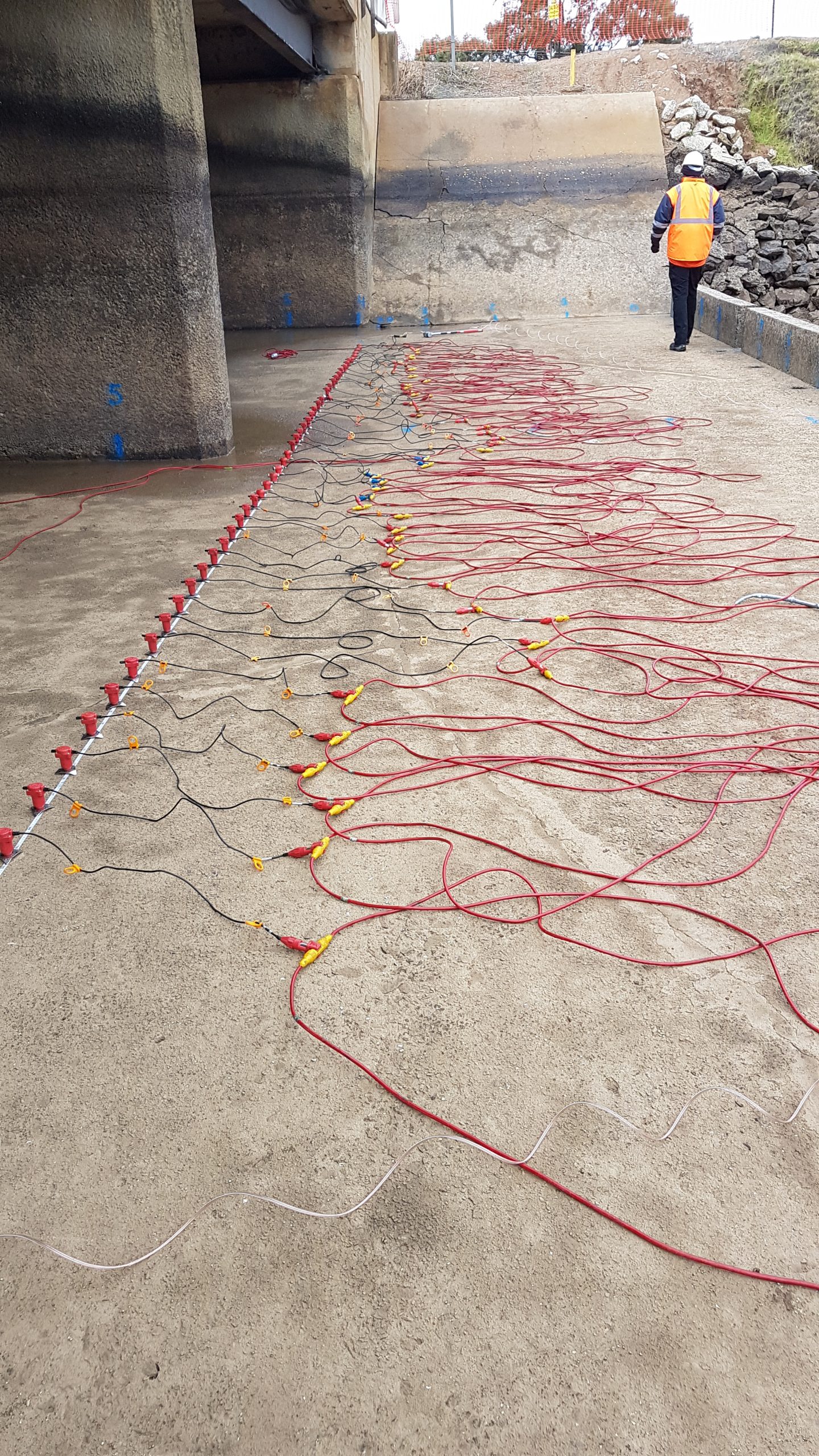
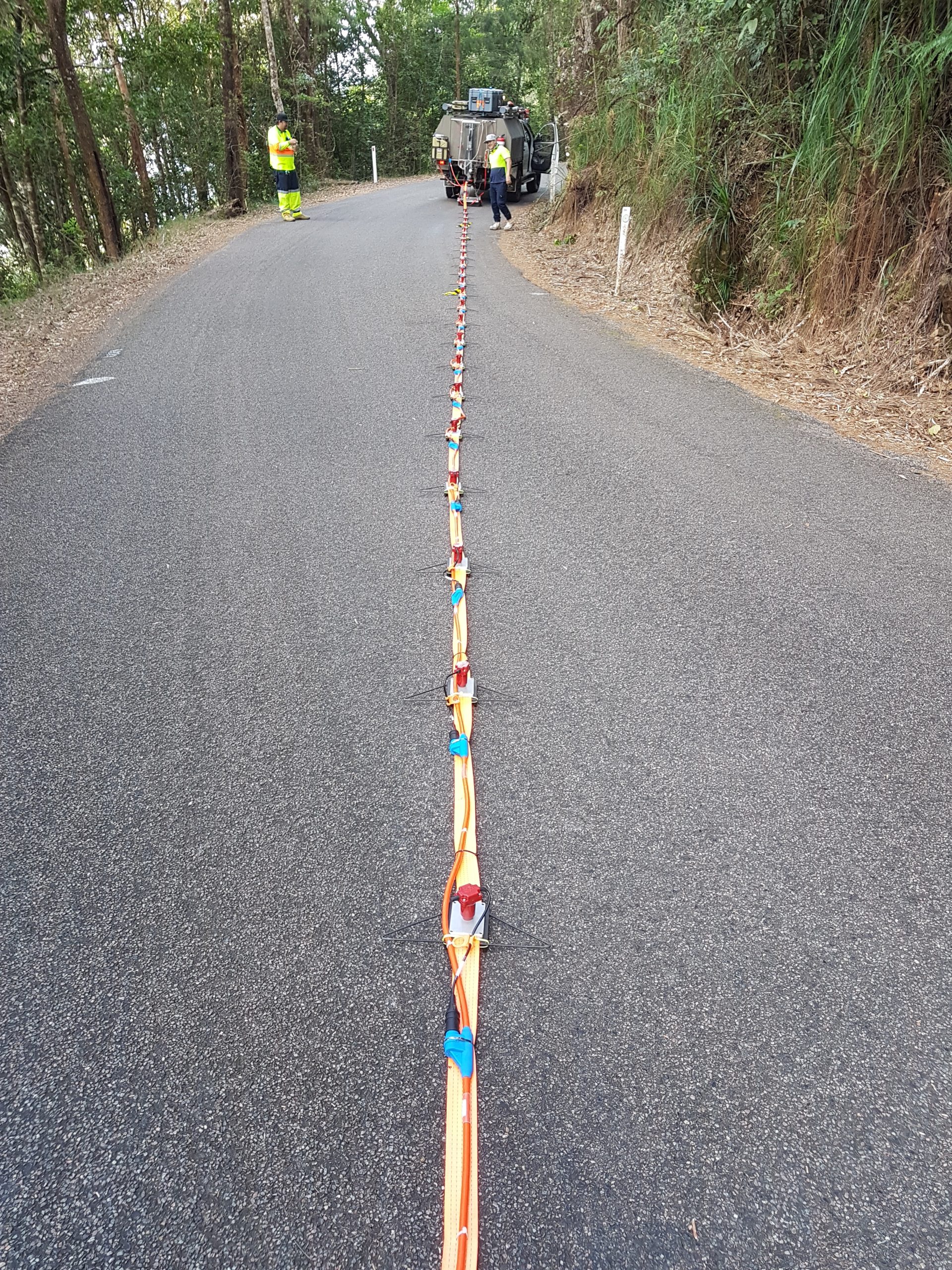
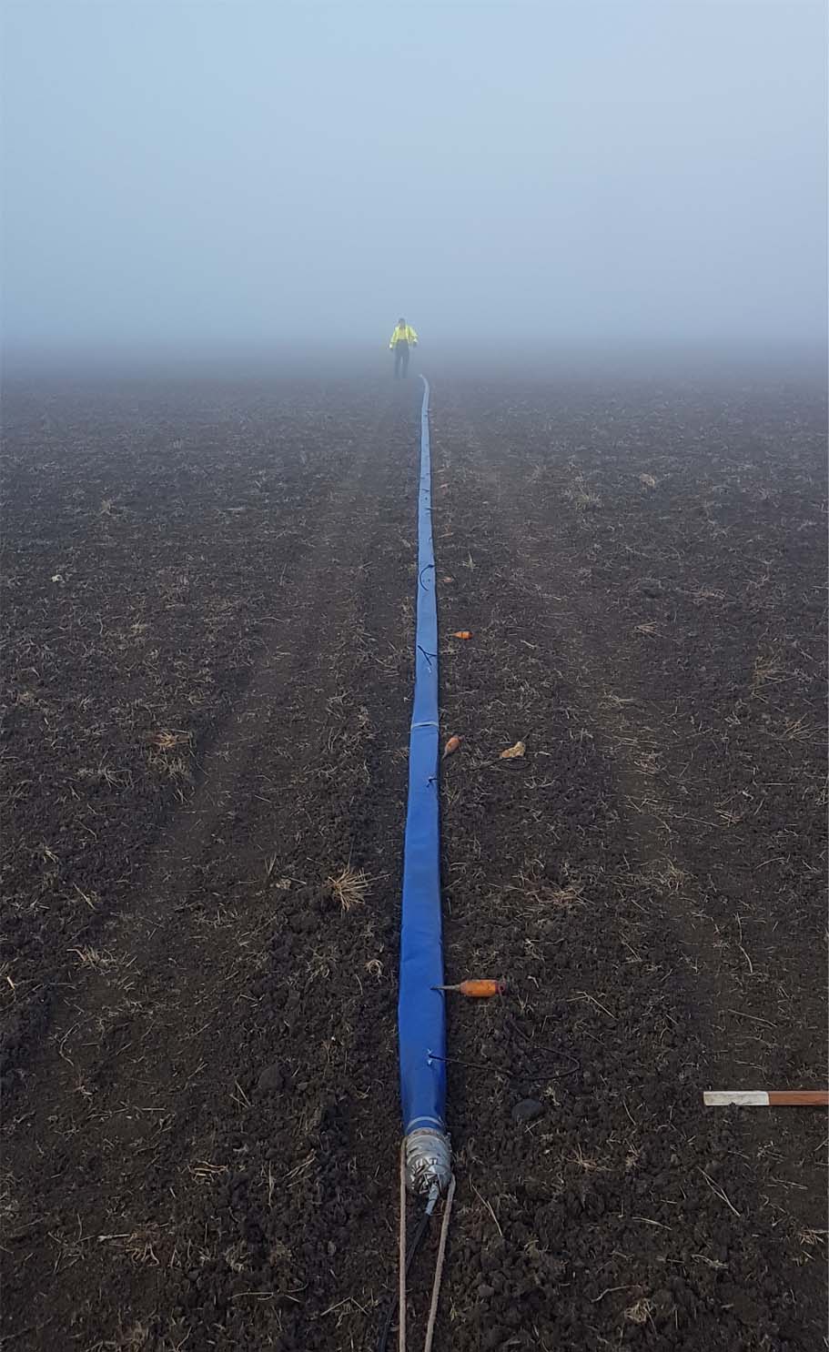
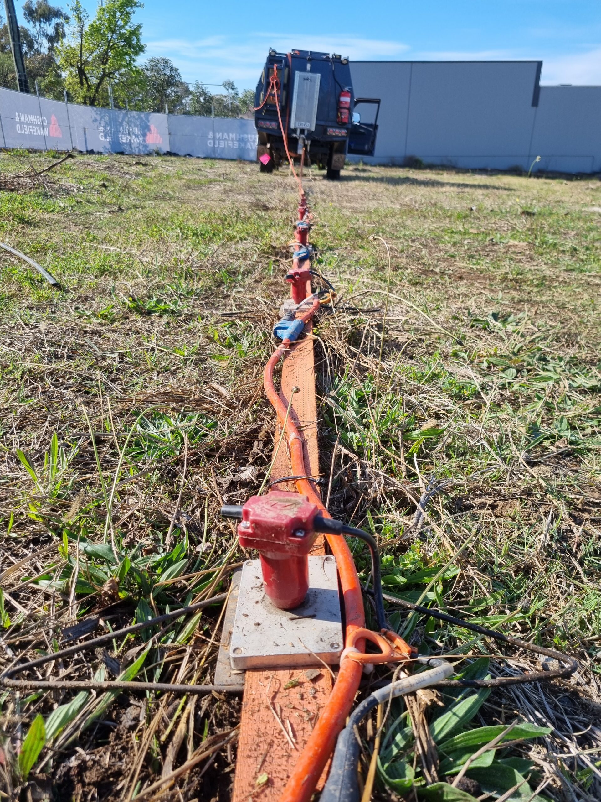
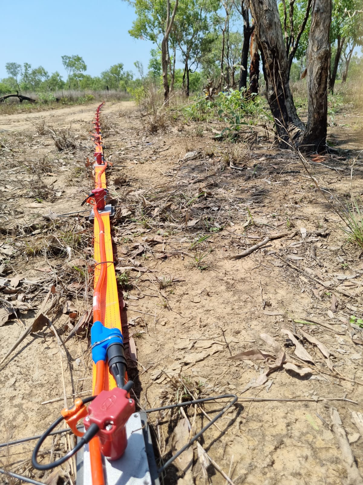
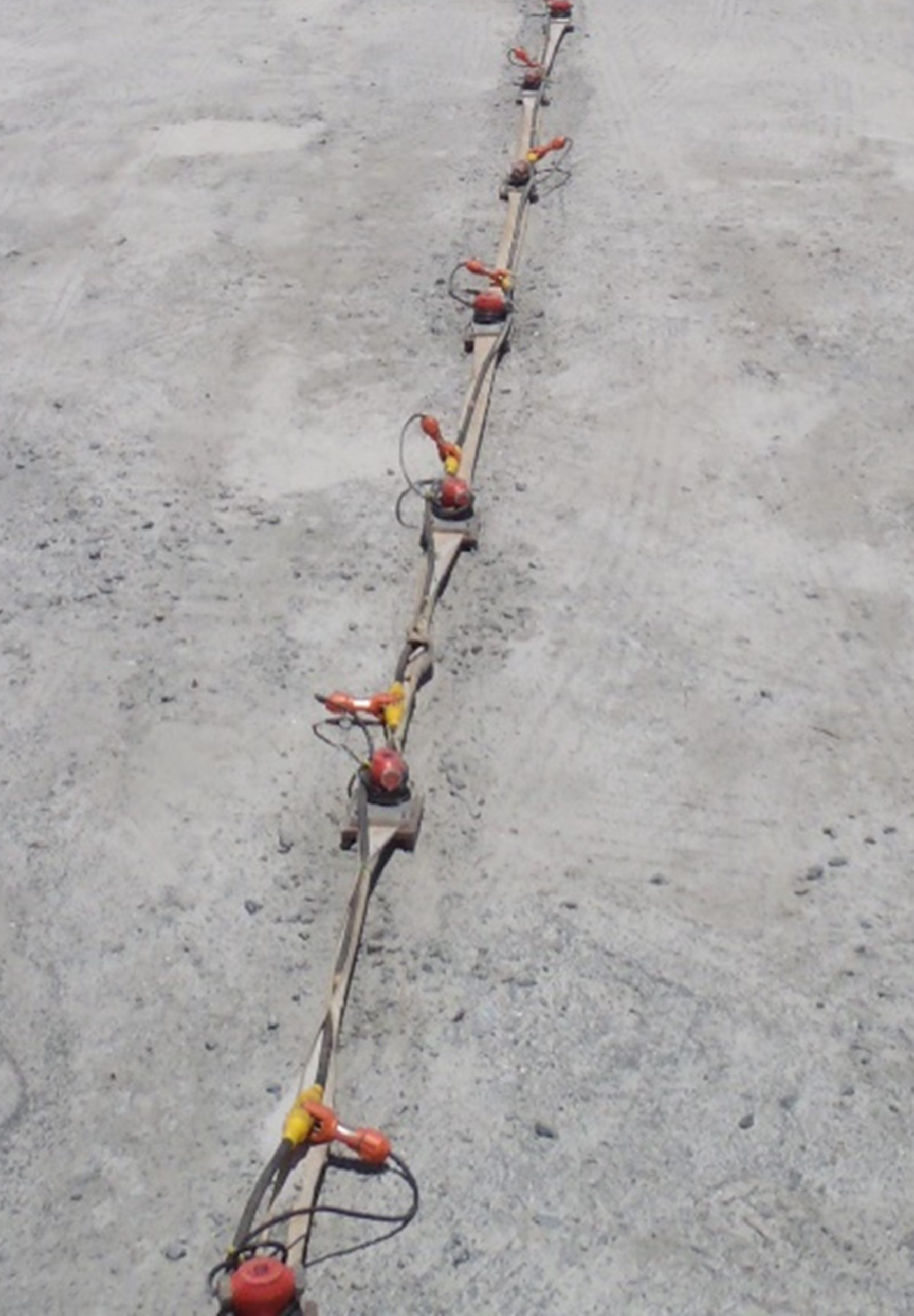
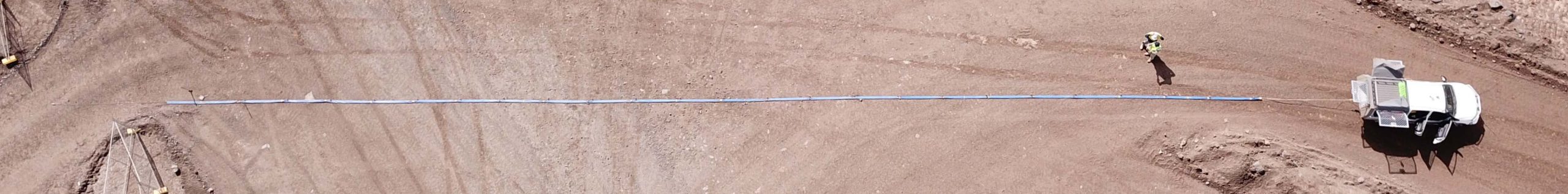
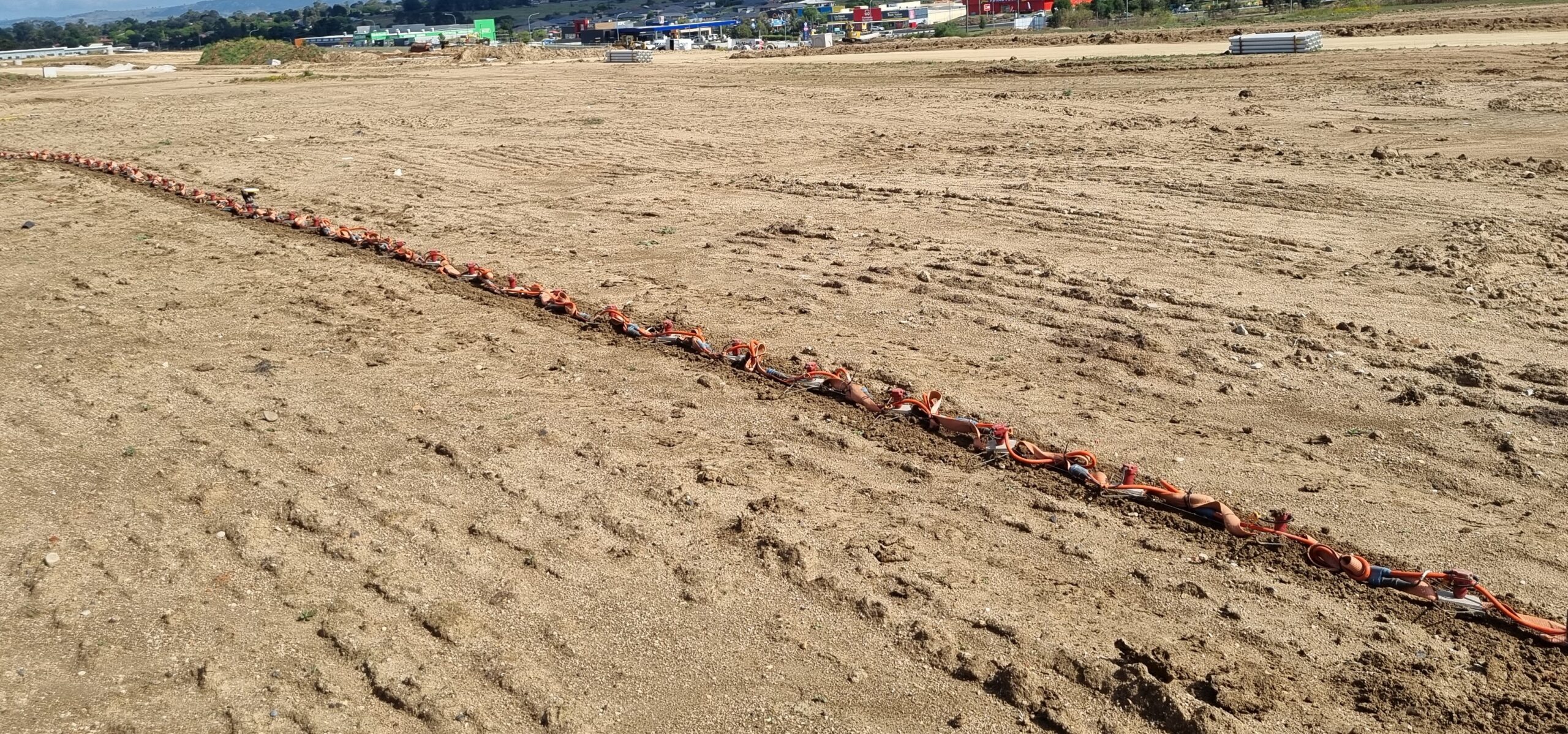
MASW (S-waves) can be deployed using the same equipment as for SRT with only changes in geometries and sometimes geophone frequency. Alternatively (commonly used), the geophones and seismic cable can be mounted on a “landstreamer”, which consists of a number of heavy metal plates linked by a Kevlar belt. The entire system is towed from a vehicle that houses the seismograph. This system is the most used deployment for the acquisition of 1D soundings for the creation of a 2D profile. There is also an option to deploy the array as a towed streamer and spiked geophones (as for SRT). This is a compromise between the acquisition speed of the “landstreamer” and the high signal/noise ration of the SRT.
Example 1: Sample of MASW 2D profile from a series of 1D soundings, showing the highly variable depth to rock and the lateral extent of layer inversion (i.e., Stiff Clay over Soft Clay), which was missed by the BH. 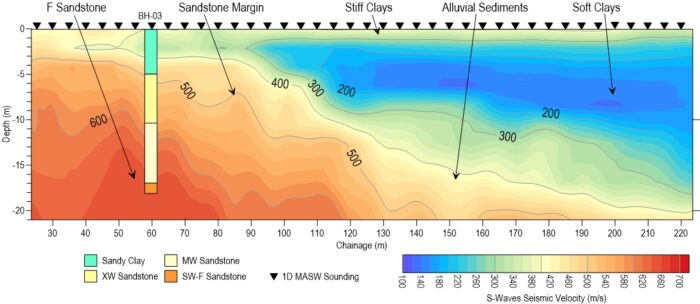
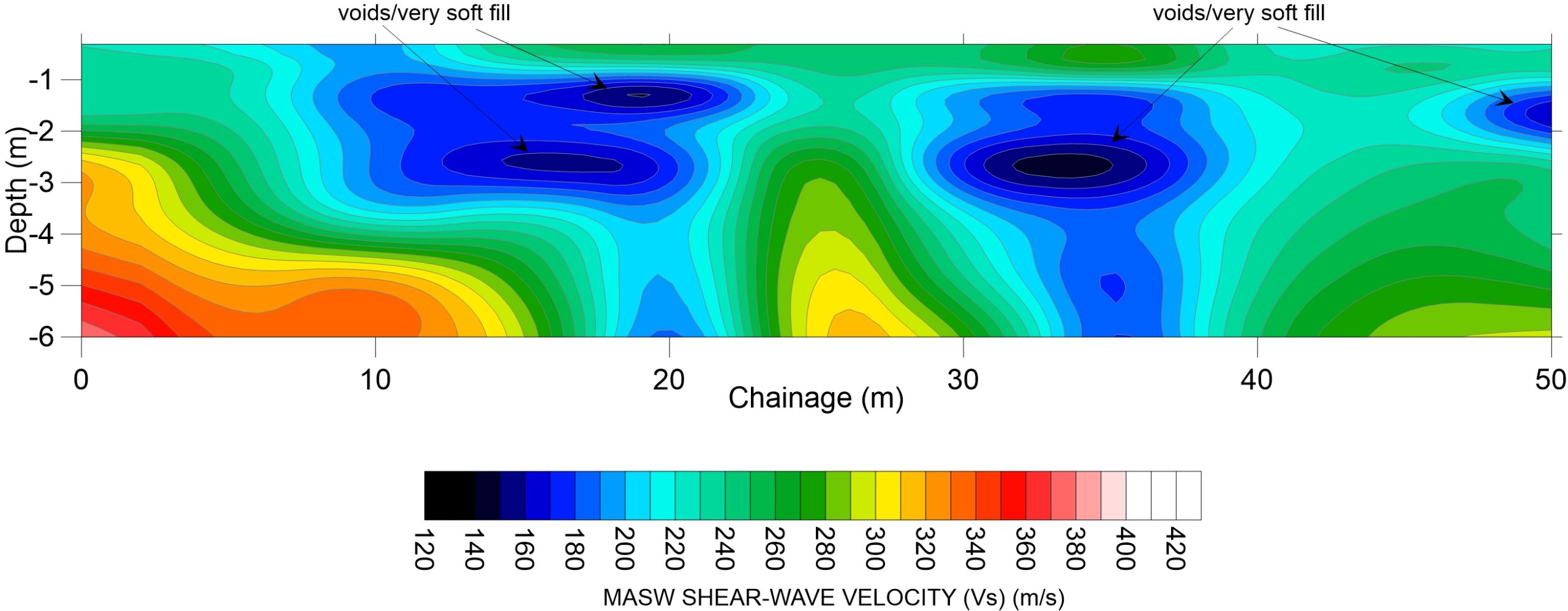
Example 2: Sample of MASW 2D profile from a series of 1D soundings, showing the presence of voids/soft fill.
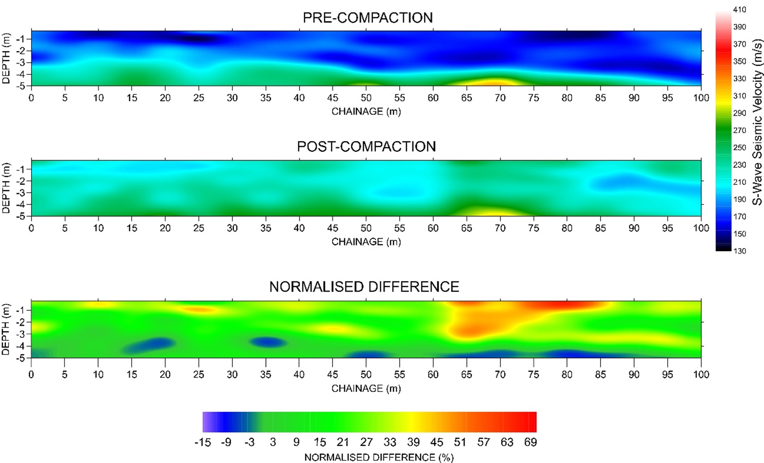
Example 3: Sample of MASW for Pre and Post compaction and normalised difference. The investigation was carried out to evaluate the efficacy of dynamic compaction and establish the ideal parameters (i.e., weight, height and spacing).
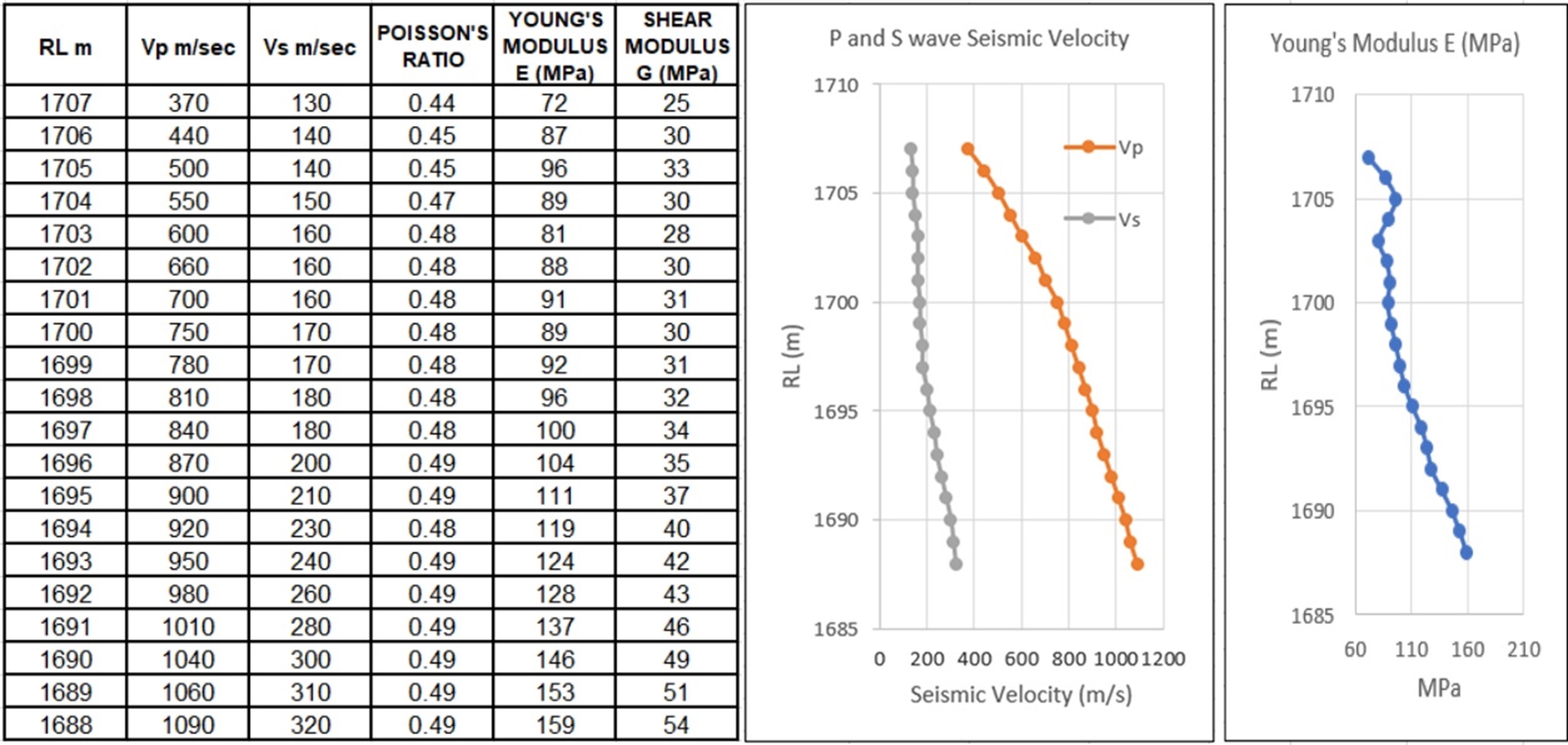
Example 4: Sample of tabulated geotechnical parameters: Poisson’s Ratio, Young’s Modulus, and Shear’s Modulus. This is possible when both MASW and LSR (i.e., P and S waves) are concurrently acquired.